
Article No. : 21
My Bio & Scientific Articles [HERE]
###
These based-day notes has been published in my LinkedIn account under tag #Wind_Energy_Version_2 & I though it’s a good idea to collect them in one article. It will be updated periodically.
###
Part 1
Date: 18 Jun 2022
I have postponed the project named as #Ocean_Power_Version_2 temporarily. There new developments related to new wind turbine technology that I worked last week for a vital reason.
It’s ironic & weird that what we have learned in past as experience is a cumulative blocks for scientific evolution tower for humankind welfare.
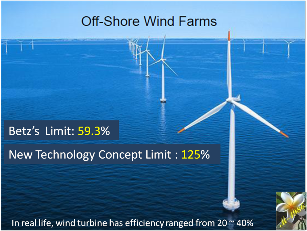
No doubt that renewable energy applications will replace fossil fuel in near future, but one of the challenges that faced countries , is the low efficiency especially for solar & wind systems.
Today, we may introduce our new concept of wind technology which can be a real game changer in the energy industry.
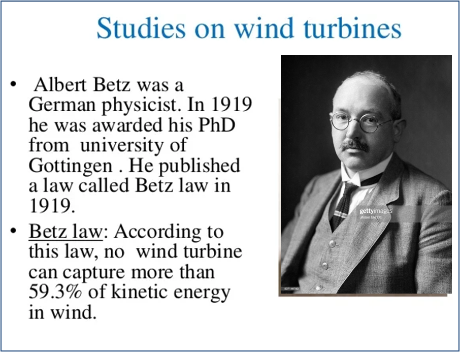
To whom who knows wind turbines well, he/she may know there is a limit of efficiency that couldn’t exceed it which is called “Betz’s Limit”. It value is equal to 59.3%
All efficiency of wind turbines in the world will work under this assumption limit & it ranged between 20 ~ 40%.
But our technology concept has a limit up to 125%
Yes, 125% without any mistake. Beyond the expectations & it’s impossible, but we prove it.
The physical equation has been established.
CFD engineering simulation validated our claims.
.
It may be technology breakthrough or even miracle for energy industry in the history of 21st century.
I’m so excited about it & that’s the reason why it will be as “Daily Notes” in my personal website & LinkedIn.
–
To be continued
*******
Part 2
Date: 24 Jun 2022
Betz’s Limit was considered as the maximum theoretical efficiency of wind turbine system. It has been stated by brilliant German physicist Albert Betz in 1919.
In simple words, it’s related to find the value of blade speed which gives us the optimum & maximum efficiency in specific conditions.

I had know about this limit when I published my 1st article about wind nergy in 2016 named as #Ingenious_Techniques_for_Increasing_the_Power_of_Wind_Energy-Technology [LINK]
In those old times, I wasn’t asking myself;
why there is a efficiency limit at first place for wind turbine?!
Also, I didn’t know how to use engineering simulation software perfectly, so it was only speculative ideas based on my scientific knowledge.
But Now, I understand Betz’s limit more than well with engineering simulation skill & that’s lead me to find the light of proposed technology which is able us to penetrate the crack on the thick cement wall which. It let us to exceed the Betz’s limit beyond the expectation.
You can’t make any progress in future unless you learn & understand the our experiences of past.
–
To be continued
*******
Part 3
Date: 29 Jun 2022
There are two classification of wind turbine in the world;
1) Bare Turbine: This is more popular system all over the world (e.g. HAWT).
2) Ducted (Shroud) Turbine: still not reach the large scale project (commercial stage).
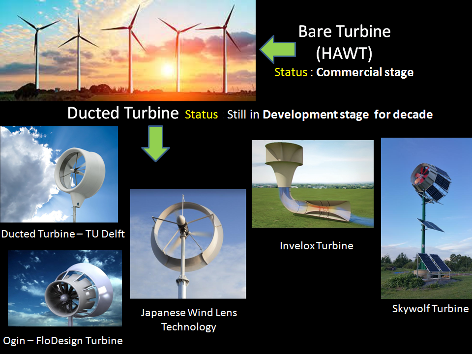
The scientists & researchers believed that ducted turbine can supreme the Betz’s limit & posses all market shares from conventional wind turbine (e.g. HAWT), but due to some technical difficulties in high altitude (to gain more energy), they failed to success.
One of the challenges faced ducted turbine is high drag force for creating vortex.
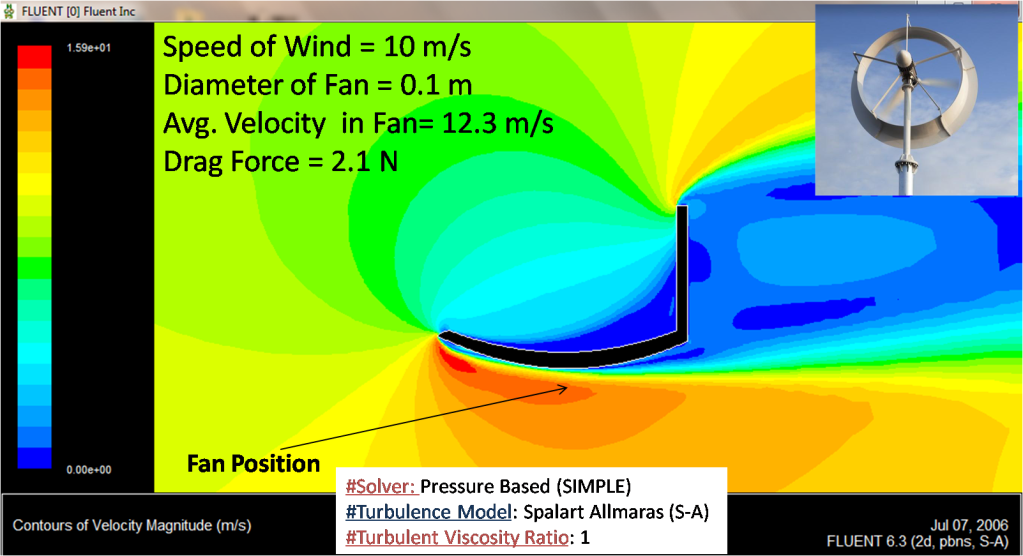
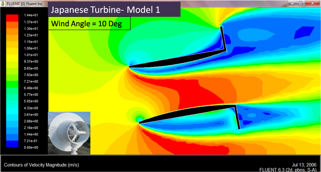
Here we have example of Japanese ducted turbine, named as “Wind Lens Technology” & I have tested by using CFD simulation software by assuming the diameter of fan is 0.1m & wind speed is 5 m/s.
The CFD result of Japanese turbine gives us:
Avg velocity = 7.75 m/s (in the position of fan)
Min Pressure = -24.6 Pa (in the position of fan)
Drag force = 2.42 N (in all walls)


Our new concept for the same diameter gives us these results:
Avg velocity = 7.76 m/s
MinPressure = -24.5 Pa
Drag force = 0.79 N_
As you noticed there is a drag reduction up to 67% & that’s definitely will solve one the challenges for the promising future of ducted turbine to solve global energy demand.
–
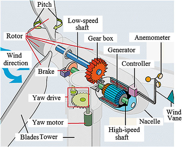
HAWT: Horizontal Axis Wind Turbine
To be continued
*******
Part 4
Date: 8 Jul 2022
Breakthrough: HAWT Power multiplied by 7.4 times

When I was working on CFD simulation of wind turbine, I noticed a strange phenomenon which is contradicts with physical laws that I knew.
I asked why that’s happen & how we can control this phenomenon to utilize it in our aim to increase the efficiency & effectiveness of my new wind shroud turbine.
The only way is to test many designs & draw a pattern of the phenomenon behaviour to understand & analysis the parameters (i.e. length) which affect on the performance of wind turbine.
After several cases, we found our unique design. It’s my 2nd idea concept after I started this exciting journey.
The test was made for wind speed of 10m/s & the average velocity on fan position was has reached up 19.5 m/s.
That’s mean the power magnification in respect to HAWT will be 7.4 times.

I have made a CFD technical table compared my found with Japanese shroud turbine (model 1 & 2).
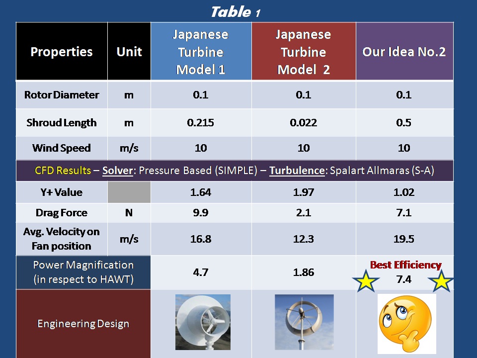
That’s really a relief after hard working, as we found something extraordinary.
HAWT: Horizontal Axis Wind Turbine
Note:
Japanese shroud turbine (Wind Lens Technology) is belong to Riamwind company (LINK) which technology was co-developed with some professors in Kyushu University (Japan).
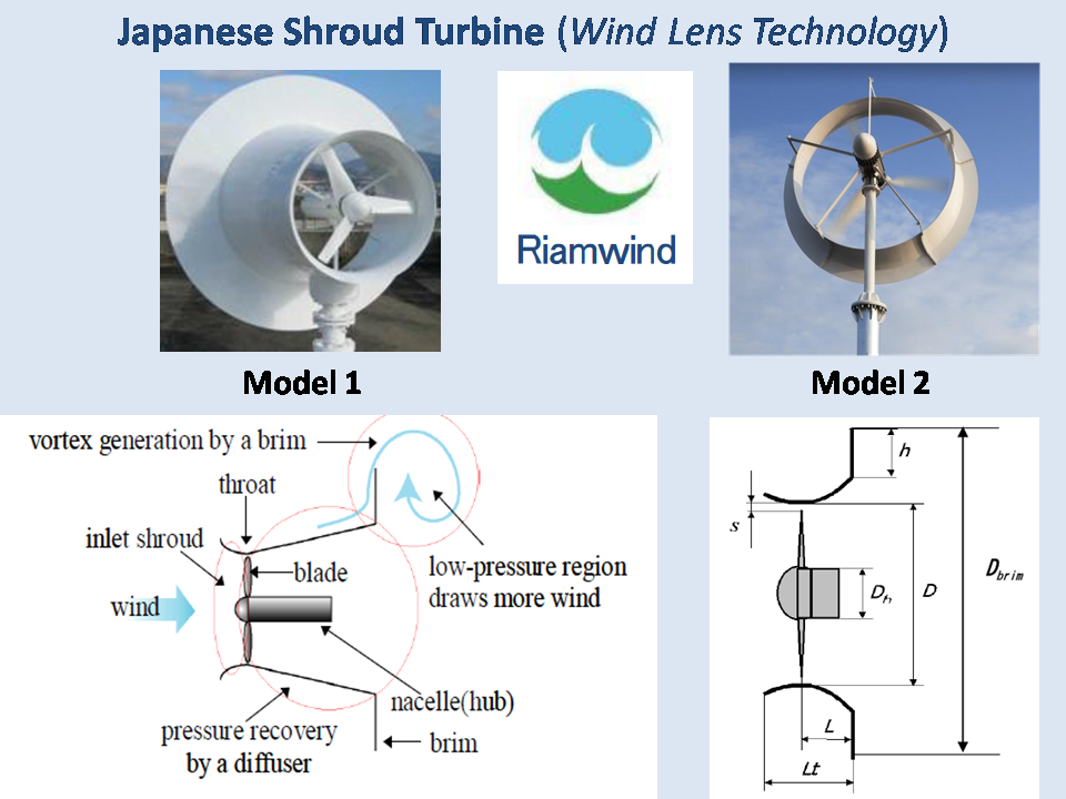
I tried to comply with the same design of their dimension as possible as I could to test it by using CFD simulation to be as reference of my progression about new idea.

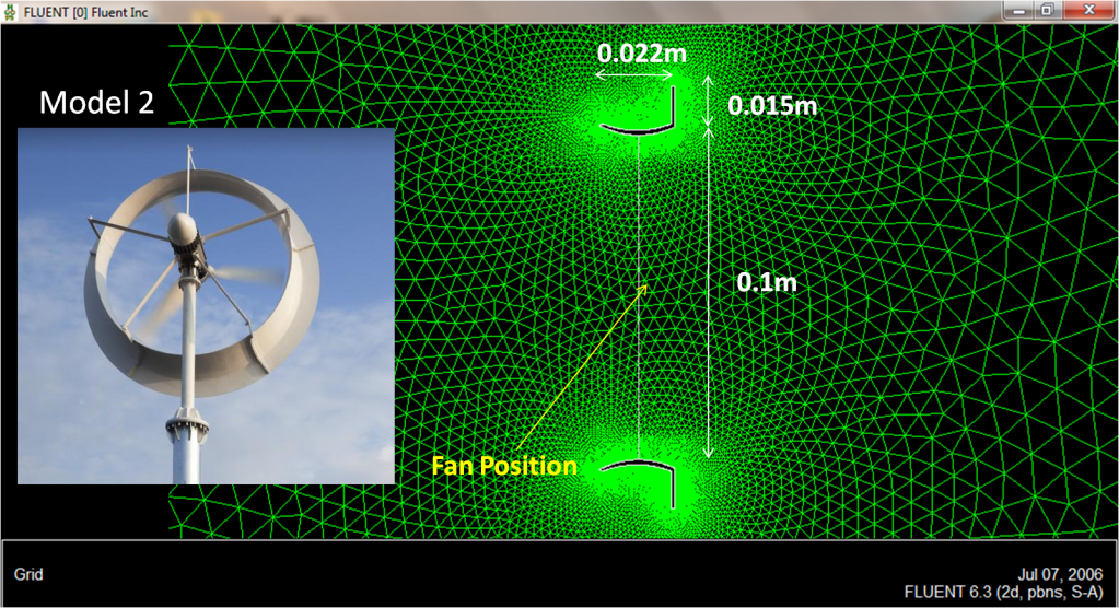
In part 3, we simulate 1st model of their technology & here we have done the same thing with 2nd model.

To be continued
*******
Part 5
Date: 11 Jul 2022
Optimization
After we found our technological concept of shroud wind turbine, we should find the best design which has a high operation performance. In another word “We are optimizing our design”. Which means: we will compare our design with itself.
We are seeking to have:
1) More electrical power with
2) Less drag force on the system.
There are many design parameters that affect those two objectives, so let us begin our investigation.
–
Parameter (1) : Effect of Angle 1
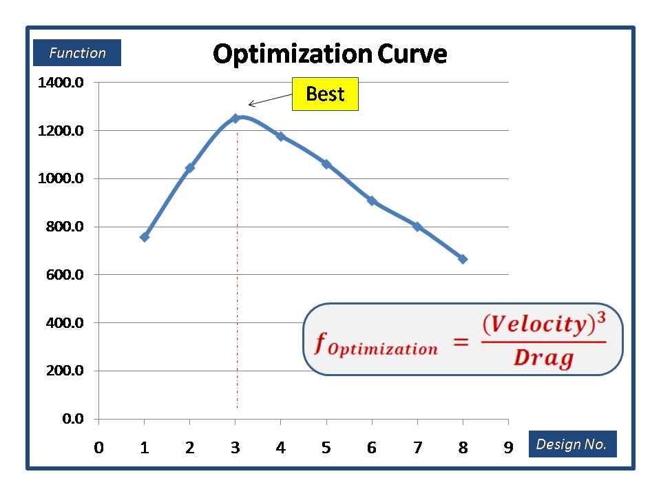
I have made many tests using CFD simulation software to know how the average velocity on hypothetical fan position & drag force can be as you see from curve graph of figure (15).

To combine velocity & drag in one equation, we established which may be called “Optimization Function”.
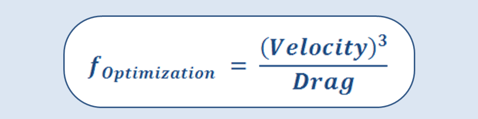
We know that power has a direct proportional relationship with velocity cube.
So, in figure (17) we plot a curve graph for several designs with the optimization function. It concludes that design No.3 was the best compared with other.

Note:
If you remember from figure (9) in part (4) or fig (18) now, we compared Japanese turbine with design No.5 which the drag force equal to 7.1 N. But now we may consider using design No.3 as it have drag force of 4.66 N which is less than previous design by 34%.

To be continued
*******
Part 6
Date: 15 Jul 2022
Roots of Problem
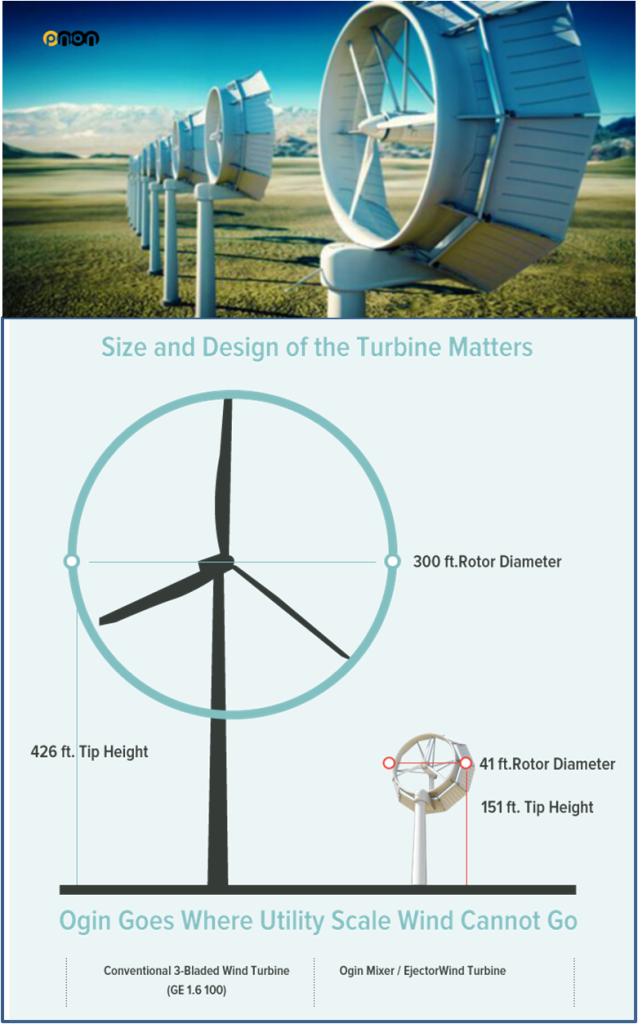
Ogin (formerly known as “Flo-Design”) was a US-based Energy Company related to ducted (shroud) wind turbine systems. They were super promising start-up from Massachusetts in the field that time, because they have a unique design which could gain 4~5 times of power compared with HAWT systems which means less size of blades for the same power.
When I started this journey, I was searching to see if their design is similar to one of my earliest designs that I have made & when I looked to their official website I realized that it has not been updated since 2017.

I was curious, what’s happen to them?
It was very hard to find a reason of shutting down their business after they collected more than 150 USD millions since 2010.
It’s like searching a needle in haystack.
Luckily, I found an article in “Boston Globe” website only [LINK], interviewing an outside expert who declared that “Ogin’s” turbine can’t work in high altitude due to high drag which means more money should spend for making sturdier strong support tower.

I was asking myself: why defunct startup/company doesn’t share their failed stories to know their problems & give a chance to other to give their solutions for them??
Few days ago, someone from my LinkedIn connections gave a list of more challenges related to ducted wind turbine that I wasn’t think about it at all & I decided to solve them one by one.-
Challenges 1: Wind Angle
According to his statement, the high power of shroud turbine may be found when the angle of wind motion aligned with the axis of turbine hub (θ= 0 Deg). After that power will reduce dramatically & get worse.
So, I made CFD test with my new concept No.2 to see how the wind angle may affect the power as you see in figure (21). It has been noticed that angle of 16° was a critical angle, that let us say: there is no useful of ducted turbine now.

Also, for comparison, I tested the Japanese turbine model 1 & 2 to see how it may affect also as we see in below figures.
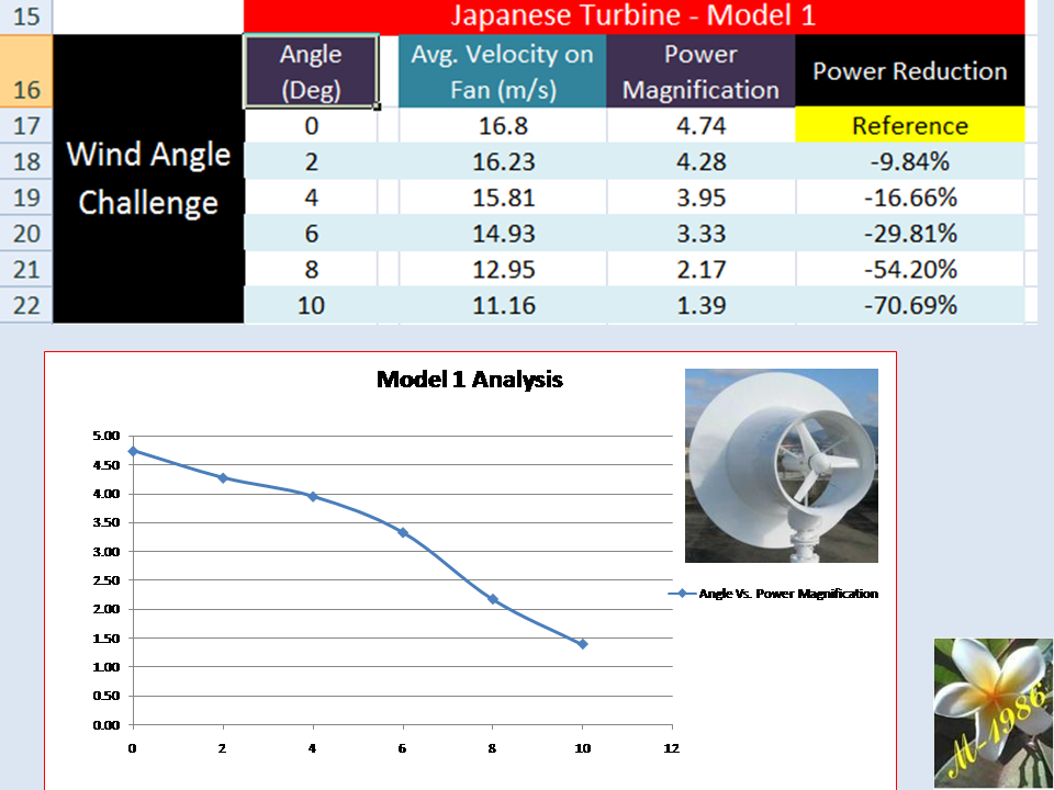
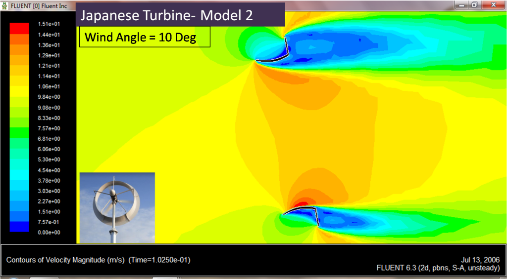
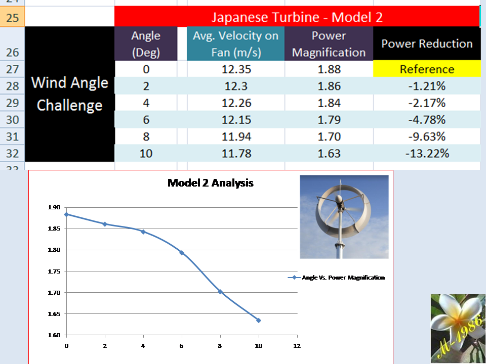
You may notice that the reduction of power in our NEW concept is approximately similar to Japanese model No.2, but remember that our concept has power magnification of 5.95, compared with Japanese model which it have 1.88 only.
HAWT: Horizontal Axis Wind Turbine
To be continued
*******
Part 7
Date: 17 Jul 2022
There was a question buzzing my brain all time related to previous part:
Why winds change its direction at first place?

From my searching, I realized 3 factors:
- Pressure difference: Hot & cold region which lead to change the density of air.
- Coriolis Effect: related to the rotation of earth.
- Friction: passing near land, tree & mountains.
They believed that, the angle of wind may reach up 20° every 5 minutes (back & forth) & worst scenario that it can be 180°.
So, I asking myself a logical question;
Isn’t better to control the natural wind direction rather than rotate huge mass of turbine blades & generator which can be more than 12 ton for 1MW of HAWT system?
There is no comparison between density of air & this heavy equipment.
We don’t need a yaw-motor at all which is responsible to align axis of turbine with wind direction, so we can save significant amount of energy.
That’s one of what I’m thinking about it now.
HAWT: Horizontal Axis Wind Turbine
To be continued
*******
Part 8
Date: 20 Jul 2022
Knowledge is power & it makes you to find solutions of our global challenges.–

I was searching in internet to find more about promising wind energy startup companies & it seems not always the big scale project can win the arena every time. We should be flexible & versatile.
They really blowing-up my mind to think about their technologies deeply.
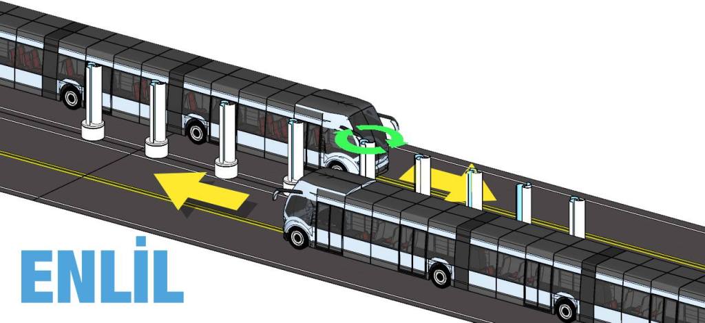
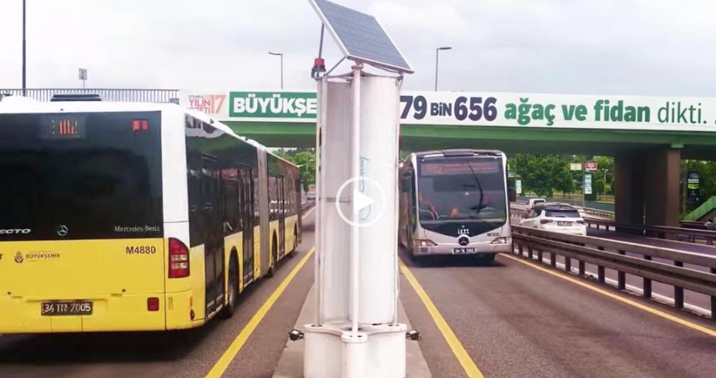
Devecitech is Turkey-based startup. It has invented a tech of the future “Enlil” The first vertical smart wind turbine designed to harvest both the energy from the natural wind, as well as that created by passing vehicles in highways.

It’s really very smart idea if we can utilized from this natural phenomenon efficiently as not always the road will have 1 street in both sides.
You may know other top 50 wind energy startups for 2022 in this [LINK]
To be continued
*******
Part 9
Date: 22 Jul 2022
Shifting Gears

It seems to me that ducted augmented wind turbine (DAWT) is unwanted topic for the repetitive patterns of failed startups to move on for years. They take grants/fund & then stopped in the middle of road because they didn’t due diligence to their work rather they get rush to predominate the market of wind industry.
I can’t blame them & I will do the same, but a wise person always learns from the mistakes of others to change the failure to succession.
I don’t give up; as I know some of reasons why they failed either by searching in internet or from my LinkedIn’s connections & there is a solutions, but the big picture is not clear to me about what should I do next if I don’t know what’s the other problems?-
So, I decided to focus my efforts in conventional HAWT system as maybe it gets some attention for wind companies, especially along this little landscape journey of ducted turbine, there was some ideas came up related to HAWT system along & some of them I was testing it by a CFD simulation software few days ago. There is a progress that I will share in this amazing article, so keep follow me.

Our strategy is simple:
- We validate our design by engineering simulation.
- We estimate the cost of construction.
- We make feasibility study of our technology & compare it with HAWT system.
After we accomplish to operate large scale project safely in somewhere, we will return back and open Pandora-Box (i.e. ducted turbine).

Wish Me Good Luck.

To be continued
*******
Part 10
Date: 27 Jul 2022
Diligence is the Key for Success
As I promised in last part, that we have a progress related to increase the efficiency of conventional HAWT system without using ducted (shroud) concept that many wind energy companies don’t like to invest on it as it’s considered as “Pandora Box” by all means.

Actually, there were 2 ideas, one of them is more costly than other; but it has an advantage to gain more power. We will talk today about the idea with lowest cost only.
Advanced HAWT No.1 (Low cost)
We have tested this concept by using three dimensional (3D) engineering simulation software (ANSYS-Fluent) & we gain more than 25% of power compared to conventional HAWT system as you see in figure (31).
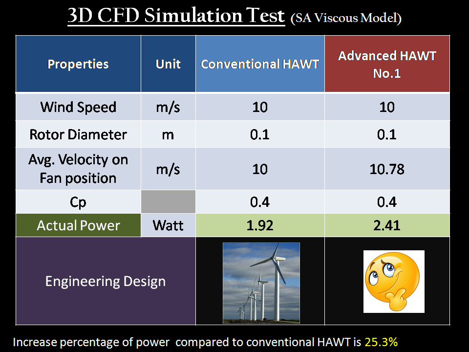
We have applied different viscous turbulence model for the same design & it gives same approximated value of average velocity on fan position & figure (32) shows the CFD residuals of our 3D test.

It’s very simple idea & all what want to do is add specific device into any existing operational HAWT system in the world & it will works like magic.
Great, isn’t ?!
Definitely, the construction cost of this device is what we concerned.
We will discuss this matter in the next part, but the preliminary evaluation is very promising regards to the price of electricity (USD/KWh).
Wait us & share it to whom is concerned.
HAWT: Horizontal Axis Wind Turbine
Note:
We should mention two important things.
1) There was very big difference in average velocity between 2&3D CFD simulation test for some natural reason that I understand it well, and that’s lead me to find innovative way to overcome it. So, Idea No,2 was born from that reason but it’s very expensive. Anyway, we will discuss it later.

2) Our 3D simulation test was test under high Y+ value due to lack of powerful computer to deal with high intensity of grid meshing, but we made several tests with different grid meshing values & it seems all it has approximately same average velocity on fan position. Y+ value is very important to get accurate result & it should be less than 5.
Also, the grid size may affect accuracy of our solution which is associated with Y+ value. Figure (34) shows a sample of grid intensity to hollow circle.

The grid test results of our idea No.1 shown in figure (35) has been made for wind speed of 5m/s & it will give us the same power gain percentage of 125% for wind speed of 10m/s with neglected difference value.
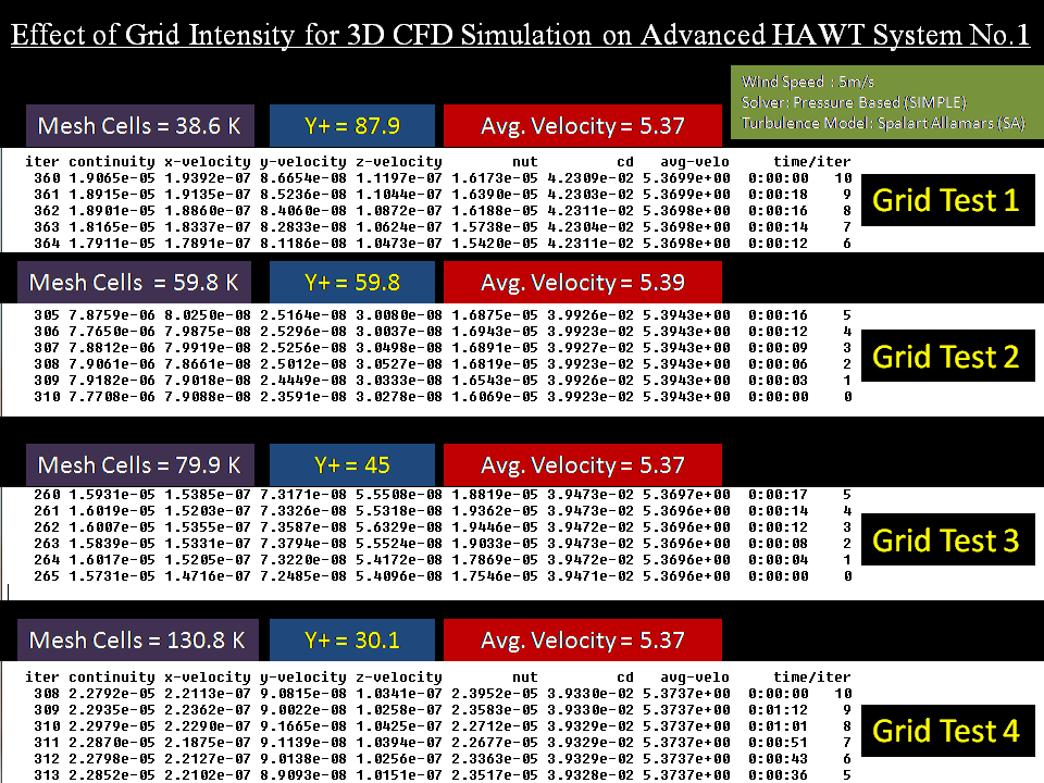
I really do my best. It’s all possible options in the table to verify my results.
To be continued
*******
Part 11
Date: 2 Aug 2022
Breaking News

As we mentioned in part 9 of our strategy to evaluate our new technology. Today we will talk about the construction cost.
To whom they don’t know, this device can be added to any existing HAWT system.
I wasn’t think it’s very hard to deal with economical cost of any new technology as the physical concept is easier than this, because you be upset for a while when you discover that your idea is not an option anymore for business even it succeed in laboratory tests.
Also, last week I have learned another type of engineering simulation related to structural model which is very crucial part in our economical evaluation. The software that I used is similar to what you saw in figure (35).

To understand what we have done, let us assume that we have HAWT system by this specification in figure (36):
The actual power (electricity) produced from the wind turbine is approximately 77 KW.
So, we know that our new concept can gain more power up to 25.3% of actual power, so the extra power will be 19.5 KWh.
We will focus only in this extra power to compare it with the construction cost of our new concept.
For on-shore HAWT, we will need 4 structural systems. (It will be discussed now)
For off-shore type will add a buoy unit, so we want 5 constructional systems.
The material used in constructional design is a mixture of polyethylene (PE) & glass fiber.

- Poly-Ethylene Properties:
Density=900 Kg/m3
Young’s Module: 0.3 GPa
Price= 5.5 $/Kg
Depression Rate = 3 Years
- Glass Fiber Properties:
Density=2600 Kg/m3
Young’s Module: 70 GPa
Price= 4 $/Kg
Depression Rate = 40Years
The total construction cost for on-shore HAWT System is 26,580 USD.
So, the annual cost of system is 1204 USD. (Remember it well !!)
We know that extra power is 19.5 KW. For 24 hours of continuous operation in period of year, the annual production of energy will be 170.6 MWh.
Now, divide the annual production of energy from annual cost, and then we may have the price related to adding new concept:


By the way, the average of electricity price over the world is 0.137 USD/KWh
HAWT: Horizontal Axis Wind Turbine
To be continued
*******
Part 12
Date: 24 Aug 2022
Creativity makes us Proud
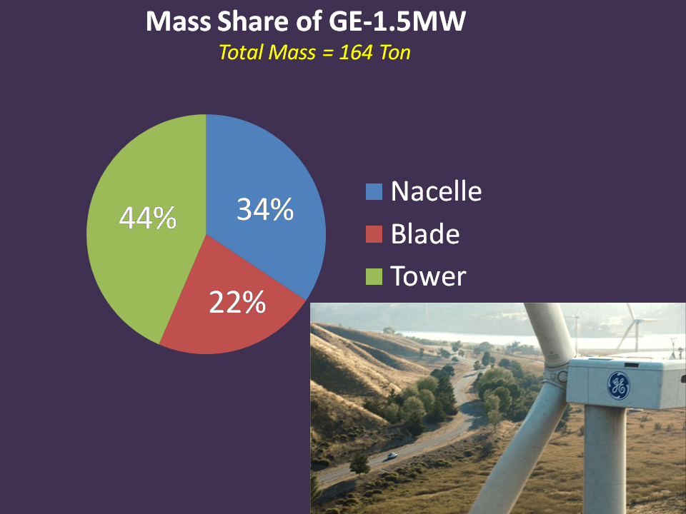
All horizontal axis wind turbine (HAWT) system has been located in high altitude which leads to increase the construction cost for supporting tower for the main components: Nacelle & Blade.
As you see in figure (37), nacelle has high percentage share of total mass of GE-1.5 MW by 56 ton.
Do you have any solution for it?
Definitely there are many ways and one of them is to make new design which maybe called as the “The Ground Wind Turbine” as you see in figure (38). It will make significant reduction of electrical cost per KWh.

How you can create such vertical wind type?
Either; by finding a natural location or creating it by using principles of physics.
Ask yourself, why in first place we have horizontal wind & then you will know how to reverse it.
We have many revolutionary applications which go against the nature such as:
- Water pump.
- Flying by plane.
- Sailing by ship.
- Planting without sunlight & so on.
All that’s happen after; we understand the natural phenomenon (i.e. experiments) & utilized it to the humanity service for better life.
To be continued
*******
Part 13
Date: 16 Jan 2023
The Luck of Hard Working
For 2 months, I was working in special project with passionate engineer from Sweden who cares too much about wind energy & wants to see the whole world (especially in developing countries such as Africa) depend on it as it’s considered as promising renewable energy nowadays.
He read this scientific article & admired my hard works, so he thinks that there is a opportunity to do great business with each other. He has the experience & I have none except ambition.
He gave me an assignment for making technical study for wind project in Sudan (Africa) to determine the levelized cost of energy (LCoE).
To do that he sent me some links for useful textbooks related to wind energy & suggested me to use 3 software in this project, which they are:
- OCTAVE (Numerical Computation).
- Global Wind Atlas (GWA).
- Q-Blade (Wind Turbine Simulation)
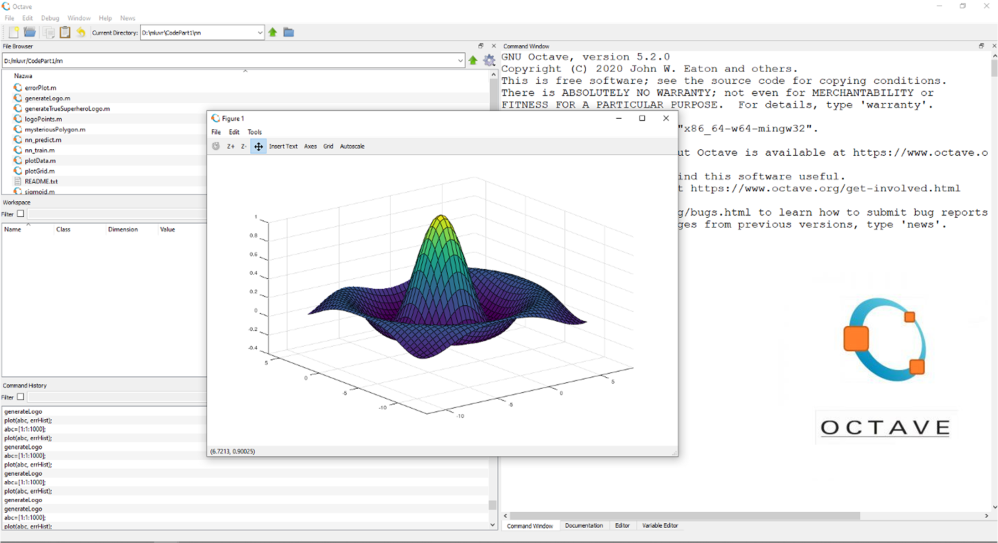
Octave: is a high-level interpreted language, primarily intended for numerical computations. It provides functionality similar to MATLAB, and can be used for signal processing, machine learning, image processing, and other applications. Octave is open- source software released under the GNU General Public License.
Global Wind Atlas (GWA) was a dataset of wind climate statistics & it was very helpful to determine which locations have the high density of wind energy. I wasn’t aware that there is such software exist which gives you full information easily rather than to read reports & make average values for each day. It was great tool for any investor wants to find suitable place to start a wind project.
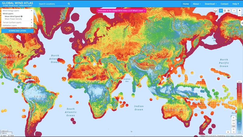
Q-Blade software was also very useful as it gives 3D approximation results of power coefficient for real test in wind tunnels. You can make many adjustments for type of airfoil by few clicks & saves really a lot of time compared to Fluent (ANSYS) software that I used before as I should wait hours for one case.

Although of its advantages, Q-Blade software can’t let you to be creative to design as its limited to traditional type in the field either for HAWT or VAWT system. I was really enjoyed this journey, even it was exhausting & worried that I can’t finish the assignment before the deadline.
I have feeling that Q-Blade is a treasure & can be more than useful to investigate but I want free time.
After I finished my 1st assignment & waiting the decision of my mentor in the beginning of New Year (2023), I did some numerical research for specific design of VAWT system, and I found way to increase the coefficient of performance up to 55%.
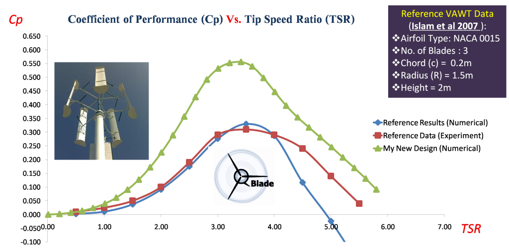
This is huge & game changer in wind industry – if it’s being validated in real wind tunnel experiments – as VAWT system always has lower efficiency compared to HAWT.
So, VAWT systems are not preferred on the investment table always for this reason.

To be continued
*******
Part 14
Date: 27 Jan 2023
The Power of Communication
Last week, Mr. Anthony Lusich (connection@LinkedIn Website) told me about exciting largest meeting on ZOOM (video-conference App) related to business relationship between investors, founders, startup & mentors for 2 hours every Wednesday.
It’s named as “ Venture-Starters” and it has been found by Mr. Mark November (connection@LinkedIn Website).

So, I said to myself maybe it’s opportunity to present my works of Energy Technologies especially in wind power systems both VAWT & HAWT.
So, I signed-up in ZOOM website & I received invitation email that meeting will be in Thursday.
I said to myself “They are disorganized people, they said it will be every Wednesday in their official website ?!! Maybe they are busy this Wednesday @25 Jan 2023.
In the day of meeting (Wednesday), I received an email told me about meeting that it will be @4.00 PM (PST: Pacific Standard Time). It is the time in west side of North America.
I asked myself what the local time would be in Sudan (Africa)?
You will not believe it.
2 AM (Morning of Thursday)
Great, so I should wake up all night for this meeting for 2 hours.
Now I understand why my meeting should be in Thursday.
For days I was trying to solve technical issues related to my webcam deice as it isn’t not working (Windows said its working properly but there is no screen at all). I googled every inch in webs without any luck.
I remember that I have mess with USB drivers last year for Bluetooth device & since then Webcam stop showing any screen.
When I realized that ZOOM meeting had 1/2 hour to get started, I give up temporarily and I should now prepared for this exciting moment & it can be game changer for my professional life.
When the meeting started I really lost there , you hear voice of someone talking without images & sometime the browser desktop freeze, so I shifted to ZOOM App which I can say it’s less worse but I realized that low speed of internet in my area is one of the reasons.
After closing browser desktop, things get better in ZOOM app.
But, … I wasn’t aware where I’m?!!

After while, I noticed there is a button titled by “Room”.I remember that Mr. Anthony Lusich told me about Rooms & participants can join to any interest 30+ rooms that he/she like such as ,
- Accelerators
- Business-to- Business/.consumer (B2B B2C)
- Disruptive Technology
- Climate/Environment.
- Women founders.
- Coaches and other fields.
so, I searched and I found Energy/Power room.
I was late, but I found people who are really encouraging you about what are you doing. It was a relief.
They are treasure-mine that can be the light of hope in dark tunnel.
Thanks for whom give me his/her time & definitely I will join next time.

Funny moment
When I was join the room, I was trying to test my microphone to see if it’s working in ZOOM meeting, so I clicked un-mute button & I started talking, then I I heard someone told me “Mohamed Wait your …”. I was interrupting other person talk.
It was embarrassing moment but I apologized for them & I told him it’s my first time in ZOOM meeting & They understand. I was thought that moderator have the right to give permission to who should talk first.

We learn from our mistakes & that’s how become expert.
Next time we may prepare well after I realized there is way to upload photo of our works (Not texting only by Chatt button).
Thanks Mr. Anthony Lusich for giving your support all these months.
To be continued
Note: I joined again the next Wednesday. (Click to see hand claps @ the end of Venture Starters meeting)

*******
